SwiGO SuperSmart - User Manual
1. Introduction
The EVIQtech SwiGO SuperSmart is an advanced IoT-enabled Switch, Motor controller and Protector designed for Indian 2-module wall boxes. It controls and protects single-phase loads up to 20A/5kW with its built-in relay, or up to 40A/30HP three-phase loads when used with an external CT (Current Transformer). The device combines intelligent motor protection with smart connectivity, allowing you to monitor and control any load or motor-driven equipment locally, over WiFi, or from anywhere via the cloud.
1.1 Key Features
Convenience
- Timer-based ON/OFF control with countdown display and four preset buttons
- Scheduling with daily, weekly, and cyclic time windows
- Simple local portal to view device operation status, next schedule & logs
- WiFi network mode for local home/office control
- Cloud mode for remote control from anywhere with activity logging
- Multi-device management from a single app
- Cross-platform local access — Android app or any web browser (iOS, iPadOS, macOS, Windows, Linux)
Protection
- Over-voltage and under-voltage protection with configurable limits
- Over-current (overload) and under-current (dry-run) protection
- Maximum run duration configuration
- Float switch and flow switch support (5V DC) — tank-overflow and dry-run protection
- Relay is switched at zero crossing, so arcing is reduced and the contacts last longer
- All operations logged to confirm and for troubleshooting power issues
Energy Measurement
- Real-time voltage, current, power, and energy monitoring (V, A, W, kWh) with an accurate power sensor chip
- Session and cumulative energy metering
Other Features
- Bluetooth Low Energy (BLE) pairing for quick setup
- Master-Remote control configuration for multi-device setups
Special Features
- Local AP mode for field/farm use without any WiFi or internet
- Cloud connectivity via EVIQtech Cloud
- Firmware update capability via the app (OTA)
1.2 Product Variants
The SwiGO SuperSmart is available in four timing variants. The button timings listed below apply to the physical buttons on the device only. When using the web app or cloud dashboard, any duration in hours and minutes can be set regardless of variant.
| Model | Button 1 (Green) | Button 2 (Yellow) | Button 3 (Blue) | Button 4 (Violet) |
|---|---|---|---|---|
| EDS031 | 5 min | 10 min | 15 min | 20 min |
| EDS032 | 15 min | 30 min | 45 min | 60 min |
| EDS033 | 1 hr | 2 hr | 3 hr | 4 hr |
| EDS034 | 4 hr | 8 hr | 12 hr | 16 hr |
1.3 Technical Specifications
| Specification | Details |
|---|---|
| Rated Voltage | 250V AC 50Hz |
| Maximum Switching Voltage | 290V AC |
| Maximum Withstand Voltage | 440V AC |
| Cut-Off Voltage | Below 170V AC or above 290V AC |
| Maximum Current (Built-in) | 20A / 3HP / 5kW |
| Maximum Current (External CT) | 40A / 30HP Three Phase |
| DC Output for Float Switch | 5V DC only |
| Mounting | Flush / Surface mount in standard Indian 2-module box |
| Suitable For | Indian 2-module box (surface-mountable) |
| Standard | IS/IEC 60669-2 |
| Color | White |
| Weight | 225g |
| Dimensions | 87 x 87 x 45mm |
| Terminal Size | 2.5 sq mm x 2 |
| Warranty | 1 Year |
1.4 What's in the Box
The SwiGO SuperSmart comes ready for installation in a standard Indian 2-module electrical box. The device is designed for surface-mountable 2-module boxes commonly used in Indian residential and commercial wiring. Contents:
- SwiGO SuperSmart unit (1x) — fits standard Indian 2-module surface-mount box
- CR1220 Battery (1x) — included in box; customer to install for RTC backup
- Quick Start Guide
- Mounting hardware
1.5 System Requirements
The SwiGO SuperSmart supports two parallel control paths. Choose whichever matches your device:
Android users: Install the EVIQtech IoT app from the Google Play Store. The app provides BLE pairing, local control, and cloud access.
iOS / iPadOS / iPhone / iPad users: No app installation is required. Use any modern web browser (Safari, Chrome, Firefox) to access the device's built-in local web interface. A native iOS app is under development and will be released soon.
Desktop / laptop users (macOS, Windows, Linux): Use any web browser to access the device on the same WiFi network or via Local AP mode.
Minimum requirements:
- Android smartphone running Android 8.0 or later, OR
- iPhone / iPad running iOS 14 or later (Safari, Chrome, Firefox), OR
- Any device with a modern web browser (macOS, Windows 10/11, Linux) for local control
- 2.4 GHz WiFi network (for WiFi and cloud modes)
- Bluetooth 4.0+ on your Android phone (only required for BLE pairing / cloud provisioning)
- EVIQtech cloud account (only required for remote/cloud features)
2. Hardware Overview
2.1 Terminals (Rear)
The rear of the SwiGO SuperSmart has the following terminal connections:
- LINE → IN: Live/Phase incoming from mains supply
- N: Neutral — two terminals both marked N; use one for incoming supply neutral and the other for looping neutral to the load
- LINE → OUT: Live/Phase output to load (motor, pump, heater, etc.)
- 5V DC Red & Black wires: Float switch supply — 5V DC ONLY
- Green wire: Earth connection
2.2 Front Panel Buttons
The front panel has five buttons with color-coded functions:
| Button | Color | Function |
|---|---|---|
| Button 1 | Green | Timer — duration per variant (see Section 1.2) |
| Button 2 | Yellow | Timer — duration per variant |
| Button 3 | Blue | Timer — duration per variant |
| Button 4 | Violet | Timer — duration per variant |
| Button 5 | Red (right) | Manual OFF / Stop |
2.3 Button Combinations — System Functions
Special button combinations provide system-level functions:
| Combination | Hold | LED | Function |
|---|---|---|---|
| Green + Yellow | 5 sec | Blue blinks fast | Activate BLE pairing mode |
| Red (alone) | 5 sec | Blue LED on | Disable BLE pairing mode (if active) OR Activate Parallel AP mode |
| Violet + Red | 10 sec | Blue LED on | Remove WiFi settings, return to AP mode |
| Yellow + Blue + Red | 20 sec | Blue LED on | Full factory reset — clears ALL settings |
2.4 Fault Indicators (LED)
| Fault | LEDs | Colors | Timing |
|---|---|---|---|
| Dry-run (under-current) | LED 1 + Right RED LED | Both RED | Blinks 6s; startup grace 7s; trips after 4s |
| Overload (over-current) | LED 2 + Right RED LED | Both RED | Blinks 6s; startup grace 7s; trips after 4s |
| Under-voltage | LED 3 + Right RED LED | LED3 RED, Right RED | Continuous; trips within 7s |
| Over-voltage | LED 4 + Right RED LED | LED4 RED, Right RED | Continuous; trips within 7s |
| Tank Full | LEDs 4, 3, 2, 1 | All Red LEDs | Bottom to top, one by one, twice |
2.5 Connection Diagrams
The SwiGO SuperSmart supports six standard wiring configurations. Each circuit is described below with its connection diagram.
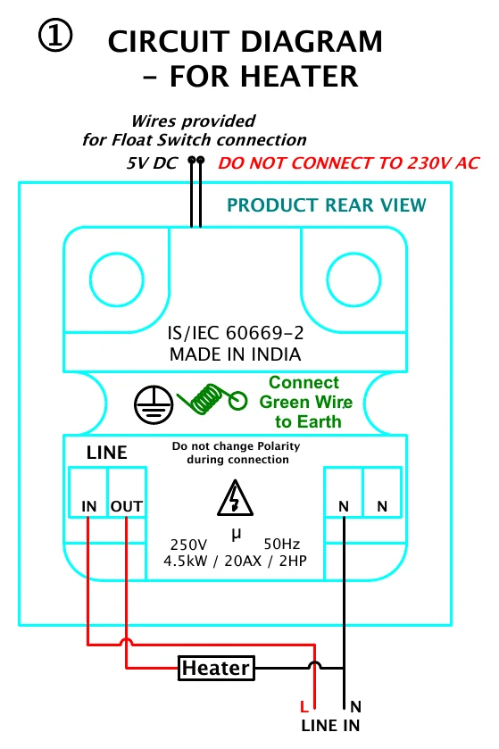
2.6 Circuit 1: Heater / Resistive Load
Use this wiring for resistive loads such as water heaters, room heaters, and immersion rods. A simple single-phase connection with live switched through the SwiGO SuperSmart and neutral passed directly to the load.
| From (Supply/Device) | → | To (Load/Accessory) |
|---|---|---|
| Mains Live (Phase) | → | SwiGO LINE → IN |
| SwiGO LINE → OUT | → | Heater Live terminal |
| Mains Neutral | → | SwiGO N (either terminal) |
| SwiGO N (other terminal) or direct | → | Heater Neutral terminal |
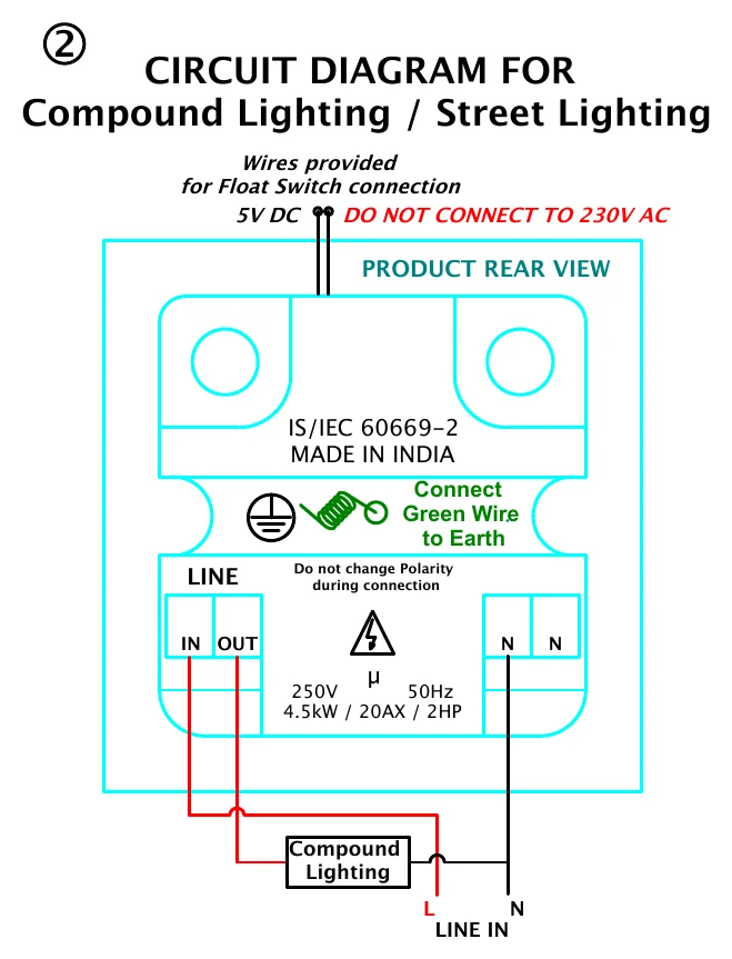
2.7 Circuit 2: Compound / Street Lighting
For compound lights, street lights, or multiple light circuits. The SwiGO SuperSmart acts as a smart switch for the entire lighting circuit, providing timer and scheduling control.
| From (Supply/Device) | → | To (Load/Accessory) |
|---|---|---|
| Mains Live (Phase) | → | SwiGO LINE → IN |
| SwiGO LINE → OUT | → | Lighting circuit Live |
| Mains Neutral | → | SwiGO N (either terminal) |
| Neutral bus / direct | → | Lighting circuit Neutral |
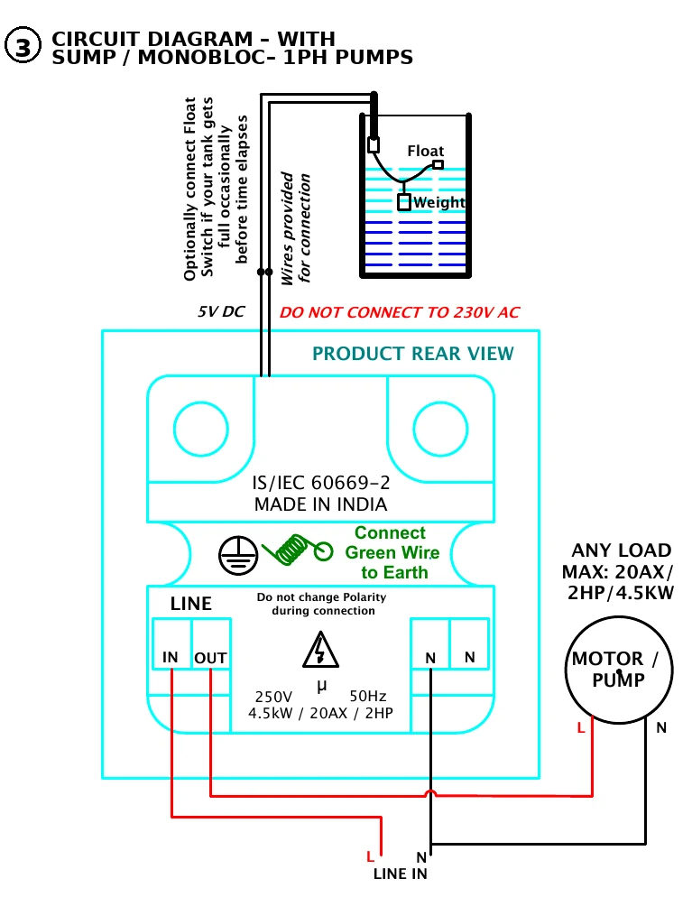
2.8 Circuit 3: Sump Pump / Monobloc / Single-Phase Motor (Most Common)
The most common wiring for single-phase motors including sump pumps, monobloc pumps, and general-purpose motors. Supports optional float switch for automatic tank-full shutoff.
| From (Supply/Device) | → | To (Load/Accessory) |
|---|---|---|
| Mains Live (Phase) | → | SwiGO LINE → IN |
| SwiGO LINE → OUT | → | Motor/Pump Live terminal |
| Mains Neutral | → | SwiGO N (either terminal) |
| SwiGO N (other terminal) or direct | → | Motor/Pump Neutral terminal |
| SwiGO 5V DC Red wire | → | Float switch wire (see Section 7.8) |
| SwiGO 5V DC Black wire | → | Float switch wire (see Section 7.8) |
| SwiGO Green wire | → | Earth connection |
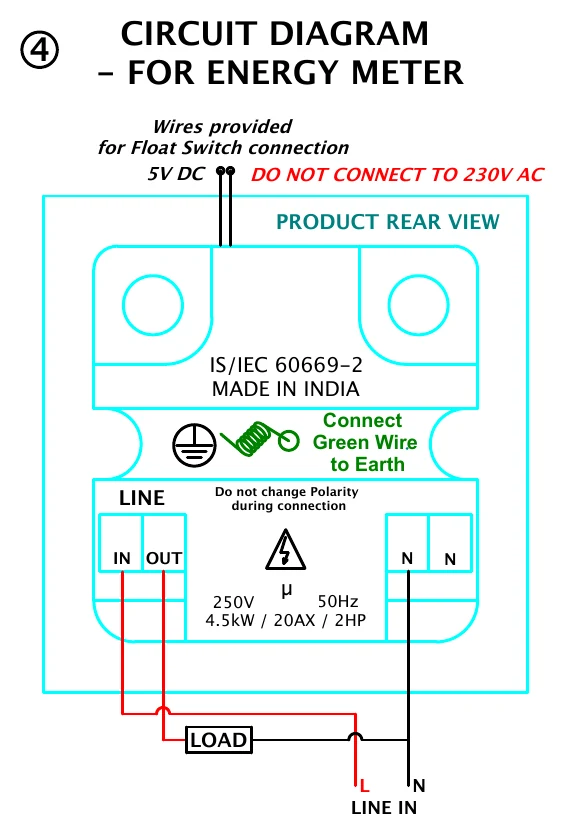
2.9 Circuit 4: Energy Monitoring Pass-Through
In this configuration, the SwiGO SuperSmart monitors voltage, current, power, and energy consumption of the load without switching it. The load remains always connected. Useful for energy auditing and monitoring equipment that should not be switched off.
| From (Supply/Device) | → | To (Load/Accessory) |
|---|---|---|
| Mains Live (Phase) | → | SwiGO LINE → IN |
| SwiGO LINE → OUT | → | Load Live (always-on) |
| Mains Neutral | → | SwiGO N (either terminal) |
| Direct | → | Load Neutral |
2.10 Circuit 5: Pressure Pump / Booster Pump — Protection-Only Mode
For pressure pumps and booster pumps where the pump has its own pressure switch. The SwiGO SuperSmart provides over-current, under-current, and voltage protection without interfering with the pump's built-in pressure-based start/stop logic.
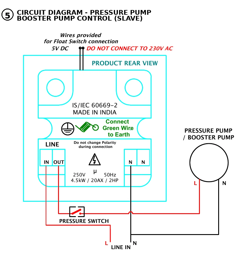
| From (Supply/Device) | → | To (Load/Accessory) |
|---|---|---|
| Mains Live (Phase) | → | SwiGO LINE → IN |
| SwiGO LINE → OUT | → | Pressure switch input |
| Pressure switch output | → | Pump Live terminal |
| Mains Neutral | → | SwiGO N (either terminal) |
| Direct | → | Pump Neutral terminal |
2.11 Circuit 6: Submersible Pump with EVIQtech Self-Starter
For submersible pumps paired with the EVIQtech Self-Starter unit. The SwiGO SuperSmart controls and protects the submersible pump while the Self-Starter handles motor starting requirements.
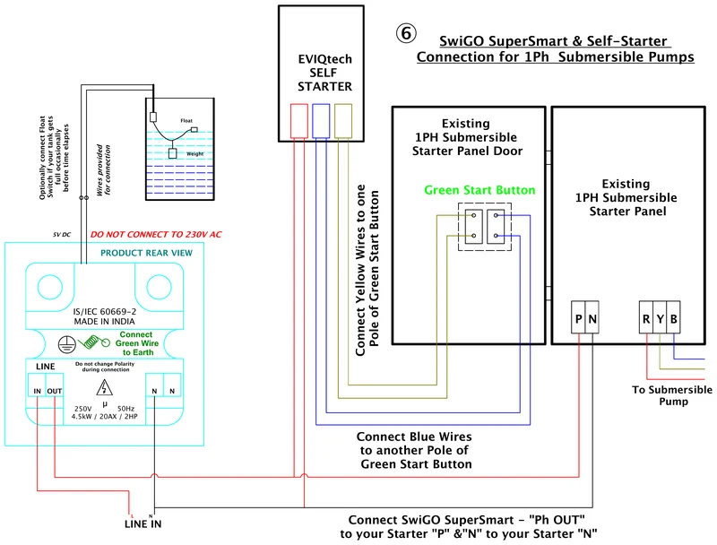
| From (Supply/Device) | → | To (Load/Accessory) |
|---|---|---|
| Mains Live (Phase) | → | SwiGO LINE → IN |
| SwiGO LINE → OUT | → | Submersible Pump Live and Self-Starter input Live |
| Self-Starter Yellow & Blue pair wires | → | Existing starter's Start button |
| Mains Neutral | → | SwiGO N (either terminal) |
| SwiGO N (other terminal) or direct | → | Self-Starter / Pump Neutral |
| SwiGO 5V DC wires | → | Float switch (see Section 7.8) |
| SwiGO Green wire | → | Earth connection |
3. Getting Started
The SwiGO SuperSmart gives you three ways to set up and control your device. Choose the path that matches your phone / device.
3.1 Choose Your Access Method
| Your Device | Access Method | What You Need |
|---|---|---|
| Android phone / tablet | EVIQtech app (recommended) | Google Play Store — search "EVIQtech" |
| iPhone / iPad | Browser (Safari, Chrome, Firefox) | No install — uses built-in web interface |
| Mac, Windows or Linux | Any modern browser | No install — uses built-in web interface |
3.2 Installing the EVIQtech App (Android only)
3.3 Browser Access (iOS / iPadOS / Desktop)
iOS and desktop users skip the app install entirely. After power-on, simply connect to the SwiGO SuperSmart's WiFi Access Point (or your home WiFi once the device is configured) and open any browser. See Section 4 for Local AP setup and Section 9 for full browser access details.
http://192.168.4.1 (AP mode) and http://DeviceName.local (WiFi mode) in your browser for quick one-tap access.
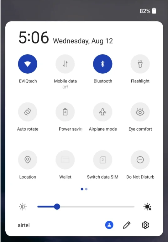
3.4 Enabling Bluetooth and WiFi
The SwiGO SuperSmart uses Bluetooth Low Energy (BLE) for Android-based cloud provisioning and WiFi for ongoing communication. For BLE pairing (Mode C, Android only), both must be enabled. For AP mode (Mode A) and WiFi mode (Mode B), only WiFi is needed.
3.5 Understanding the Three Access Modes
| Mode | Connection | Internet | Best For |
|---|---|---|---|
| A — Local AP | Direct WiFi AP from device | No | Field, farm, no router |
| B — WiFi Network | Home / office WiFi router | No | Local home / office control |
| C — BLE + Cloud | BLE → WiFi → Cloud | Yes | Remote from anywhere |
4. Mode A — Local AP Mode
In AP mode, the SwiGO SuperSmart creates its own WiFi access point. Connect and control the device directly without any router or internet. Ideal for field installations, farms, or locations without WiFi. This mode works with both the Android app and any browser (iOS, macOS, Windows, Linux).
4.1 First-Time Setup — Initial Setup Page
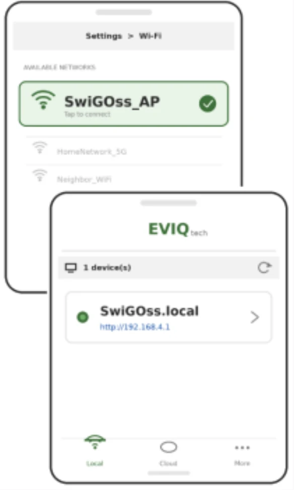
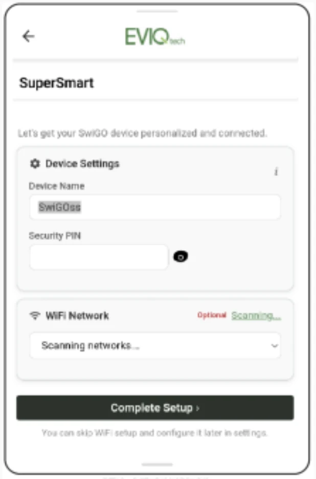
When the SwiGO SuperSmart is powered on for the first time (or after a factory reset), it presents an Initial Setup page where you create your own Device Name and Security PIN. There is no default PIN to remember — you define your own during this one-time setup.
- Android: Launch the EVIQtech app. The device appears as SwiGOss.local at 192.168.4.1.
- iOS / Desktop: Open any browser (Safari, Chrome, Firefox) and go to
http://192.168.4.1.
- Device Name — a memorable name such as "Motor", "Pump", or "Tank"
- Security PIN — a 4-digit PIN you will use every time you unlock the device
- Home WiFi Network (optional) — if you want the device to connect to your home / office WiFi immediately
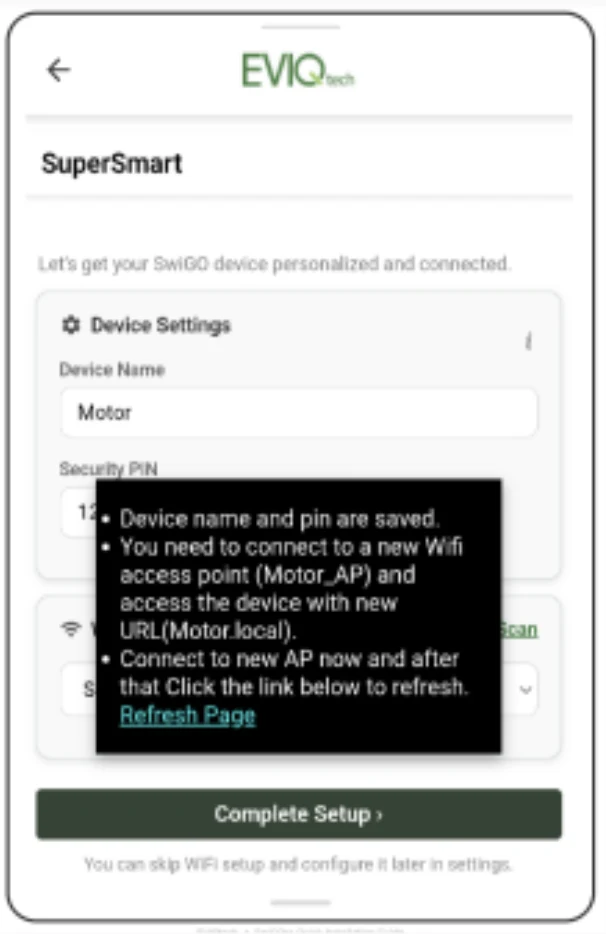
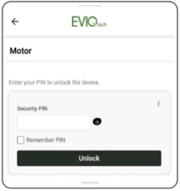
- Android: Relaunch the EVIQtech app.
- iOS / Desktop: Browse to
http://192.168.4.1orhttp://motor.local(use your chosen Device Name).
4.2 Subsequent Access in AP Mode
After the Initial Setup is complete, entering AP mode on later sessions is simple:
http://192.168.4.1 or http://DeviceName.local (iOS / desktop).5. Mode B — WiFi Network Mode
In WiFi Network mode, the SwiGO SuperSmart connects to your home / office WiFi router. All devices on the same network can discover and control it. No internet required. Works with Android app and any browser.
5.1 Setting Up WiFi Mode
You can configure home WiFi during Initial Setup (Section 4.1, Step 4) or anytime afterwards via Settings.
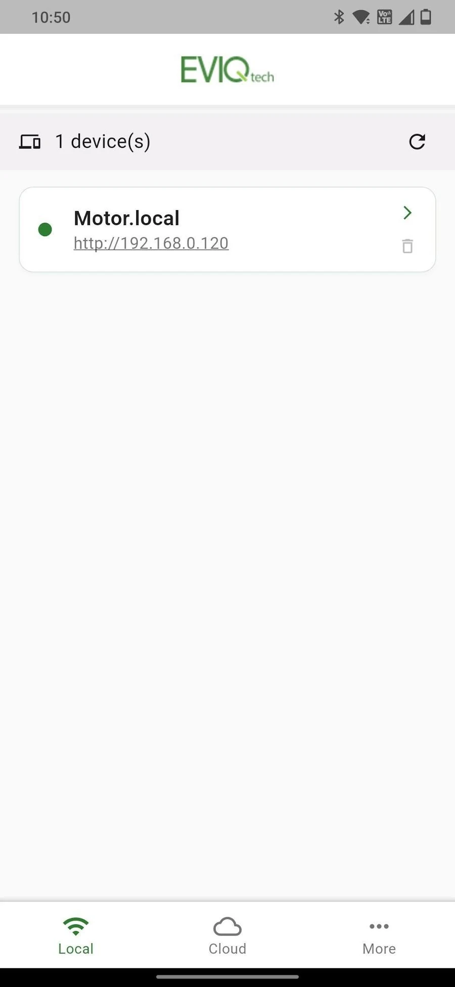
- Android: Device appears with its name and router-assigned IP.
- iOS / Desktop: Browse to
http://DeviceName.local(e.g.,http://motor.local) or the IP shown in your router.
6. Mode C — BLE Pairing + WiFi + Cloud
Mode C is the recommended setup for full IoT functionality. It uses Bluetooth Low Energy (BLE) to configure the device, connects it to WiFi, and optionally links it to the EVIQtech Cloud for remote access from anywhere.
6.1 Prerequisites
- SwiGO SuperSmart device powered ON
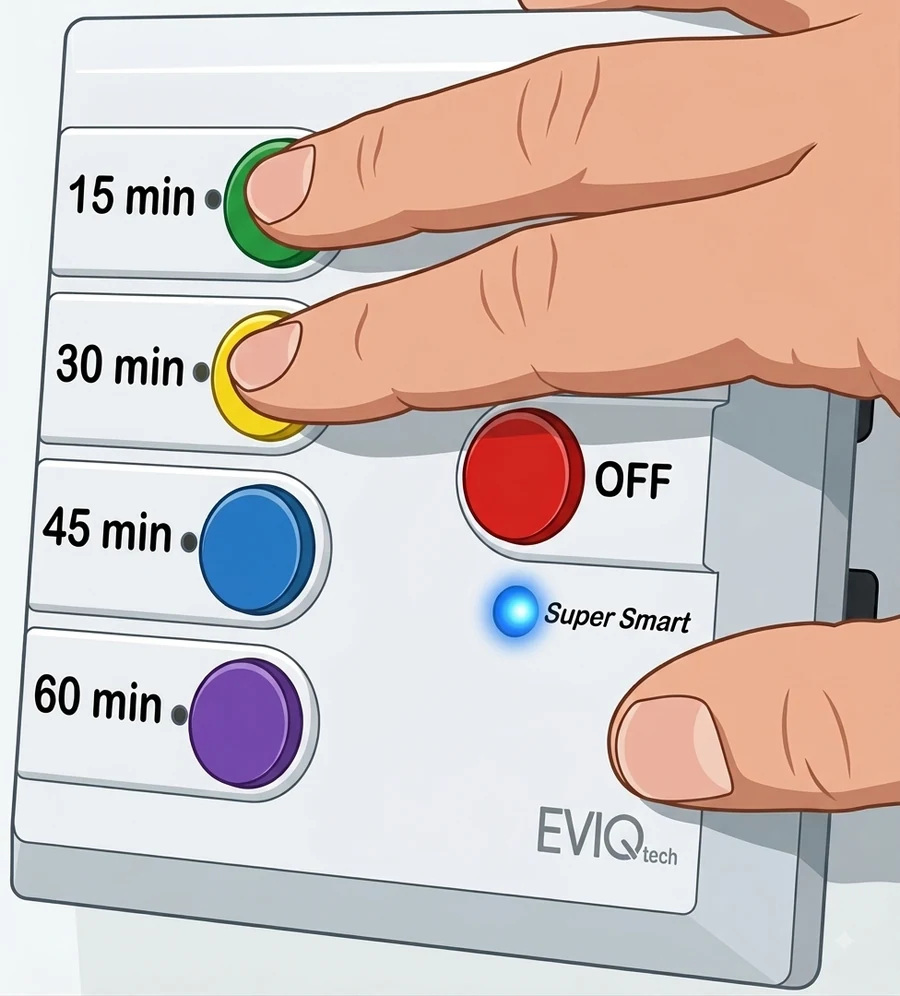
- BLE pairing mode activated: Hold Green + Yellow buttons ~5 seconds until the blue LED blinks
- Bluetooth enabled on your Android phone
- EVIQtech app installed
- Home WiFi name (SSID) and password ready
- EVIQtech cloud account email (if enabling cloud)
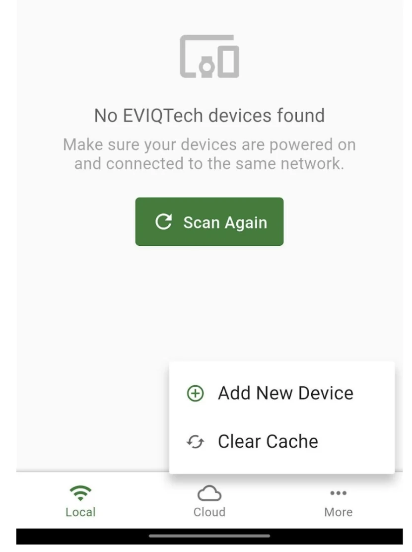
6.2 Starting BLE Scan
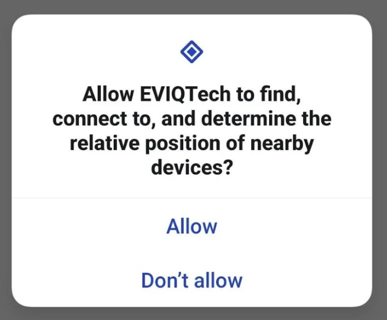
6.3 Granting Permissions
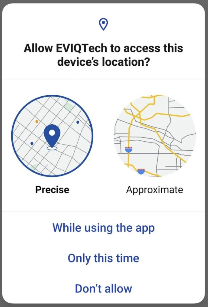
6.5 Scanning and Selecting Your Device
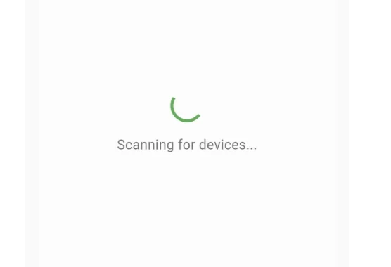
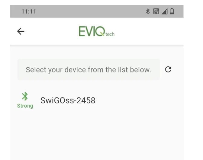
6.6 Configuring the Device (Single-Page Setup)
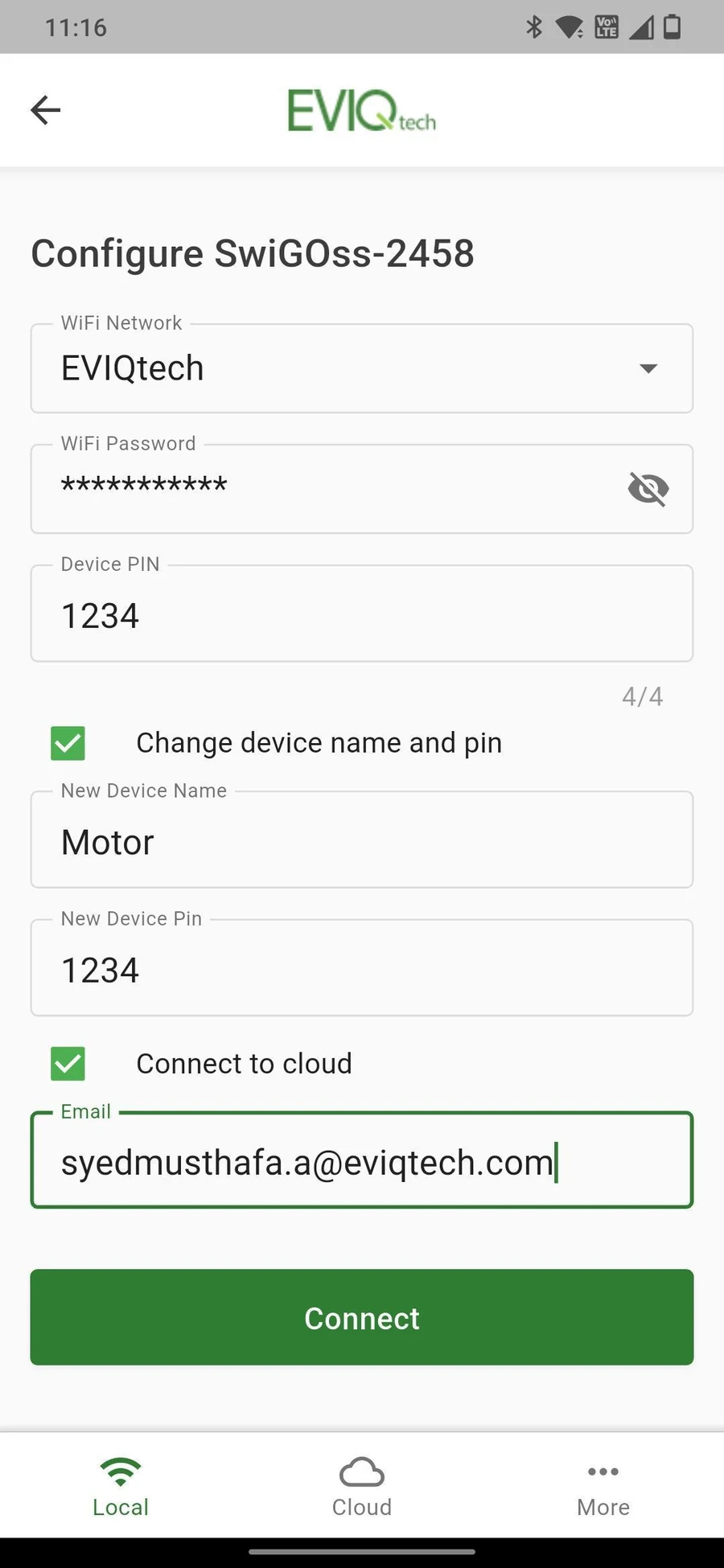
As of firmware 1.14.11 and later, device configuration uses a single unified page that matches the Initial Setup experience. Whether you are setting up via BLE (Mode C) or via the Initial Setup page (Mode A), you enter the same fields in one place.
- WiFi Network: Select your 2.4 GHz home WiFi
- WiFi Password: Enter password; tap the eye icon to verify
- Device Name: Enter your preferred name (e.g., "Motor", "Pump")
- Security PIN: Set a 4-digit PIN of your choice — this becomes your device's PIN going forward
- Connect to cloud: Check to enable cloud connectivity (optional)
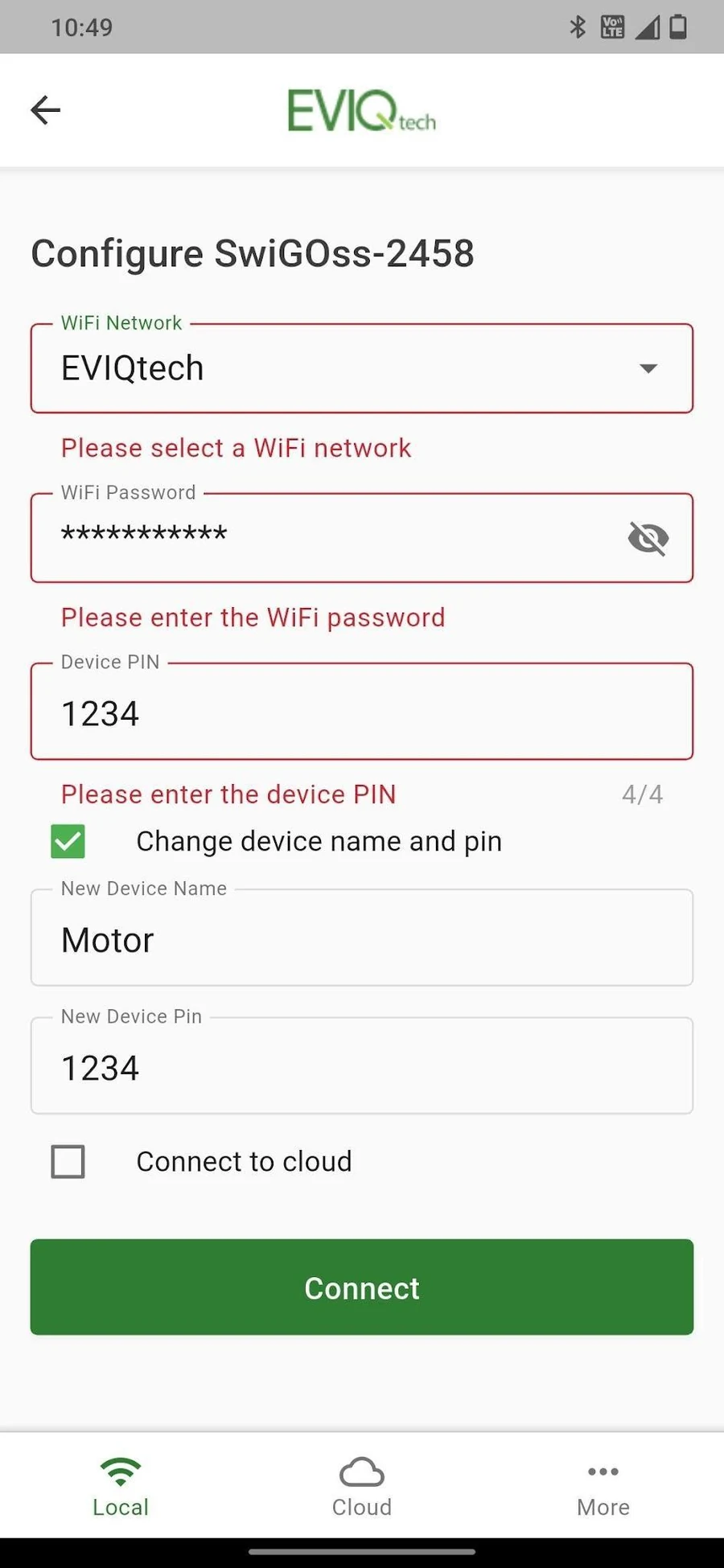
6.7 Enabling Cloud Connection
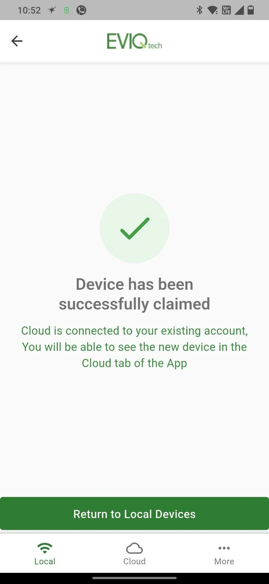
If you check "Connect to cloud" on the configuration page, an Email field appears. You can leave it unchecked if you do not plan to connect the device to the cloud.
6.9 Verifying WiFi and Local Access
7. Using the Local App Interface
The EVIQtech Android app has three bottom tabs: Local, Cloud, and More. The browser interface (iOS / desktop) mirrors the Local tab exactly, so the screens described in this section apply equally to both.
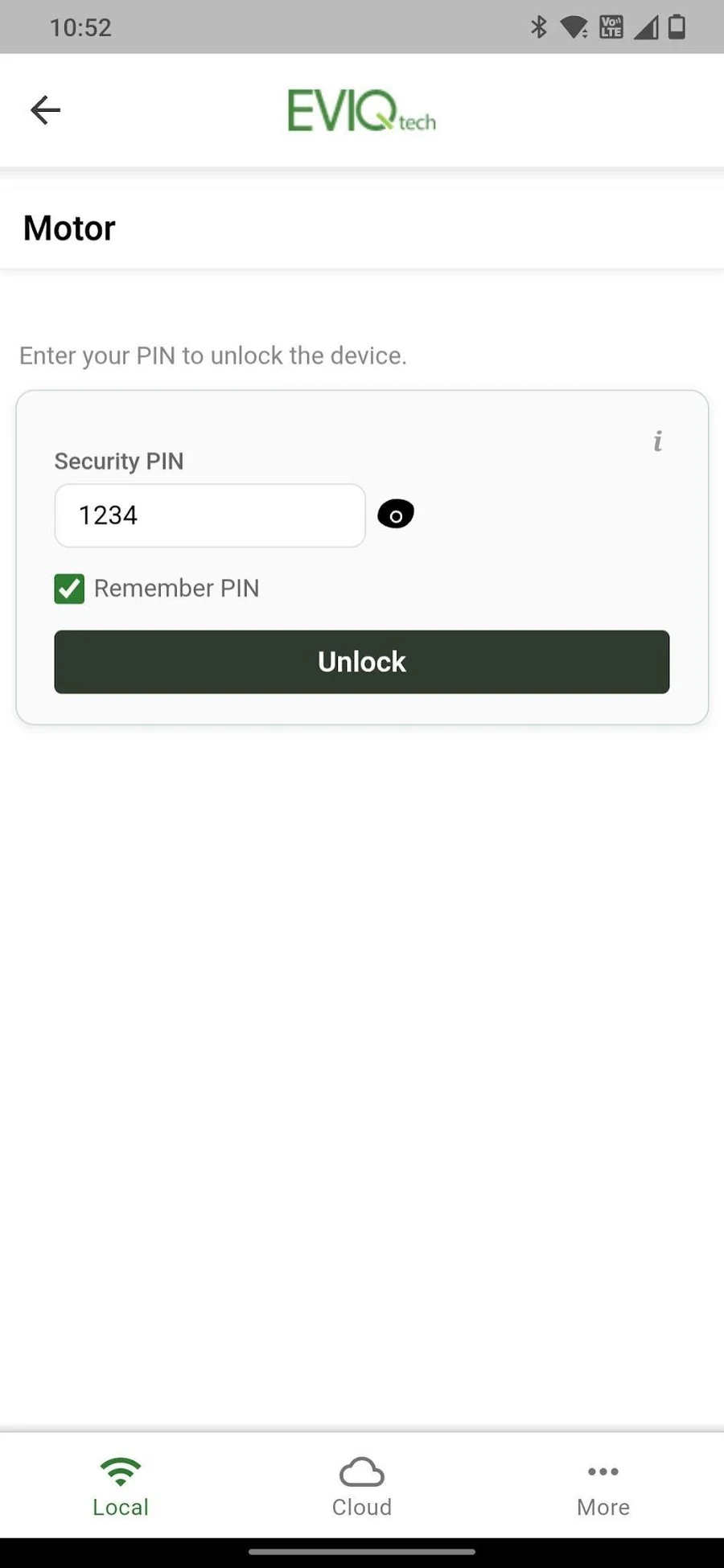
7.1 Unlocking the Device
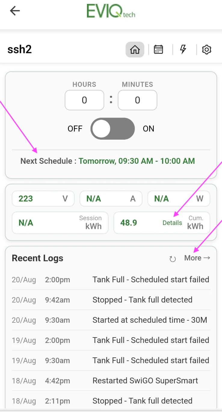
7.2 Home Page (House Icon)
- Hours : Minutes: Set custom timer duration
- OFF / ON toggle: Main power switch
- Next Schedule section: The next schedule is shown here
- Fault section: If the device stops due to a fault, the fault is indicated here
- Voltage (V): Real-time mains voltage (e.g., 230.2V)
- Current (A): Real-time current draw
- Power (W): Real-time power consumption
- Session kWh: Energy for current session
- Cumulative kWh: Total lifetime energy
- Details link (marked): Link to all recent sessions with energy
- Recent Logs: Timestamped activity log — tap "More" (marked) for full history
7.3 Navigation Icons
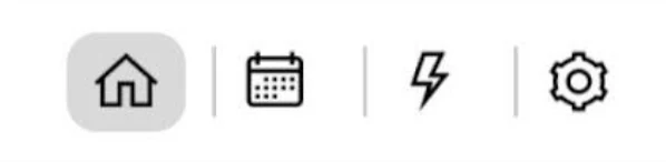
- Home (house): Main control panel (default)
- Schedules (calendar): Schedule management
- Protection (lightning): Protection settings and energy data
- Settings (gear): Device configuration
7.4 Schedules Page
The Schedules page lets you automate motor operation with flexible time-based control. Tap the Calendar icon in the navigation bar to access it. You can create multiple schedules, each independently enabled or disabled.
Schedule Configuration Options
- Schedule Type: Choose Daily (runs every day) or Weekly (select specific days M/T/W/T/F/S/S)
- Start Time: The time (HH:MM) when the motor should turn ON
- End Time: The time (HH:MM) when the motor should turn OFF
- Enable / Disable toggle: Green toggle to activate or deactivate a schedule without deleting it
- + Add Schedule: Tap to create a new schedule entry
- Delete: Remove a schedule permanently
- Is Cyclic: Check this box to enable repeating ON/OFF cycles within the scheduled time window
- ON Duration (Hours : Minutes): How long the motor runs in each cycle
- OFF Duration (Hours : Minutes): How long the motor pauses between cycles
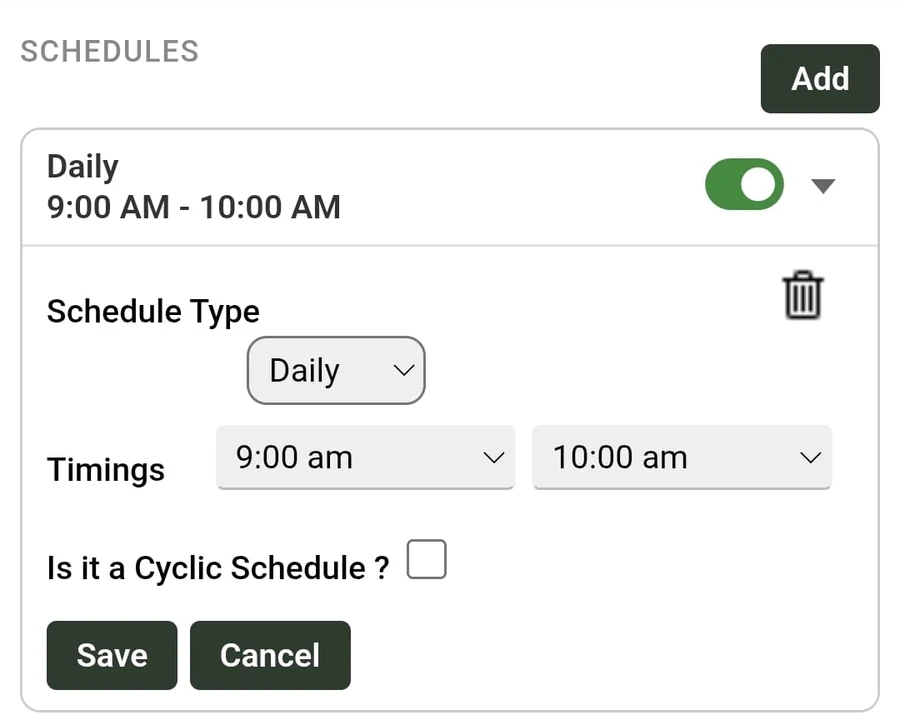
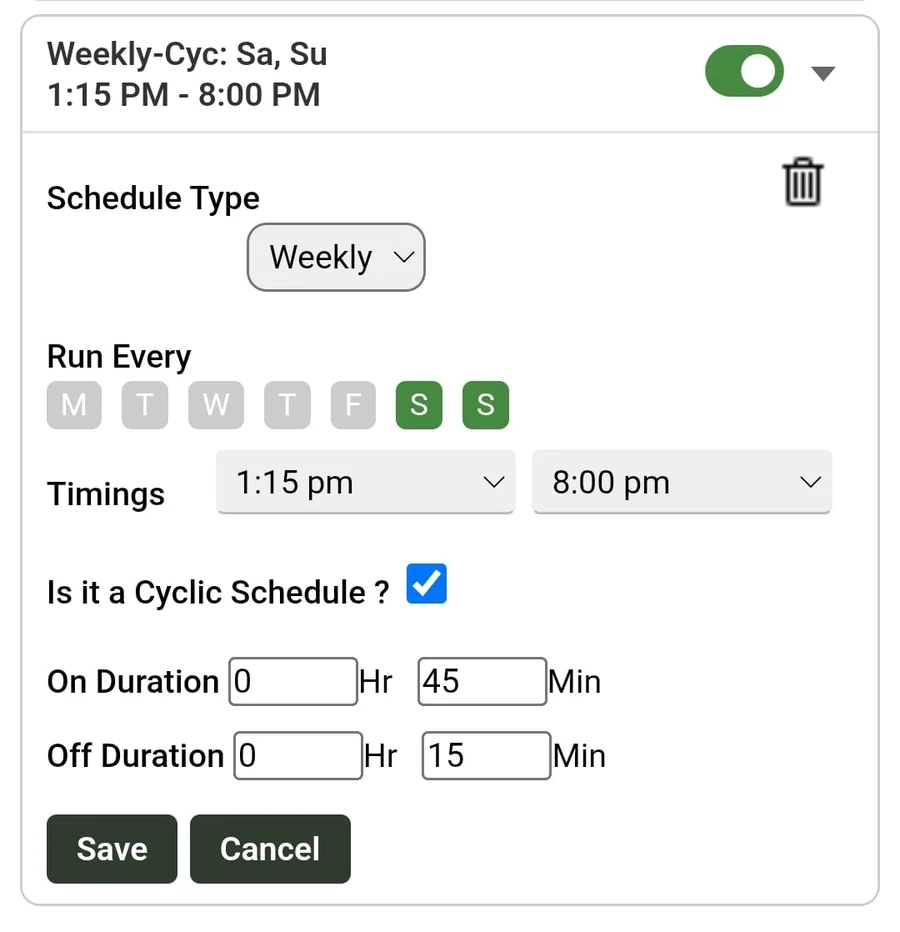
As per the schedule, the device will start and stop automatically.
Up to 10 schedules can be added in SuperSmart. Cyclic schedule options can be used to schedule more.
Note: Restart after power resumption (see Section 7.5) — if checked, the SuperSmart resumes automatically after a power outage, if the scheduled timing is still remaining.
Note: The Cloud scheduling interface (Section 8.7) is identical in functionality. Schedules configured via Cloud or Local are written directly to the device.
Cyclic Scheduling (Detailed)
When "Is Cyclic" is checked, additional ON duration and OFF duration fields appear. Instead of running continuously from Start Time to End Time, the motor will repeatedly cycle ON and OFF within that time window.
How Cyclic works: Suppose you set Start Time = 06:00, End Time = 18:00, ON duration = 30 minutes, OFF duration = 15 minutes. The motor will turn ON at 06:00, run for 30 minutes, turn OFF at 06:30, wait 15 minutes, turn ON again at 06:45, run for 30 minutes, turn OFF at 07:15, and so on — repeating this 30-on / 15-off cycle until 18:00.
- ON Duration (Hours : Minutes): How long the motor runs in each cycle
- OFF Duration (Hours : Minutes): How long the motor pauses between cycles
7.5 Protection Settings
The Protection page provides comprehensive motor and electrical protection. Tap the Lightning icon in the navigation bar to access it. Each protection type can be independently configured and has an info (i) button for on-screen guidance.
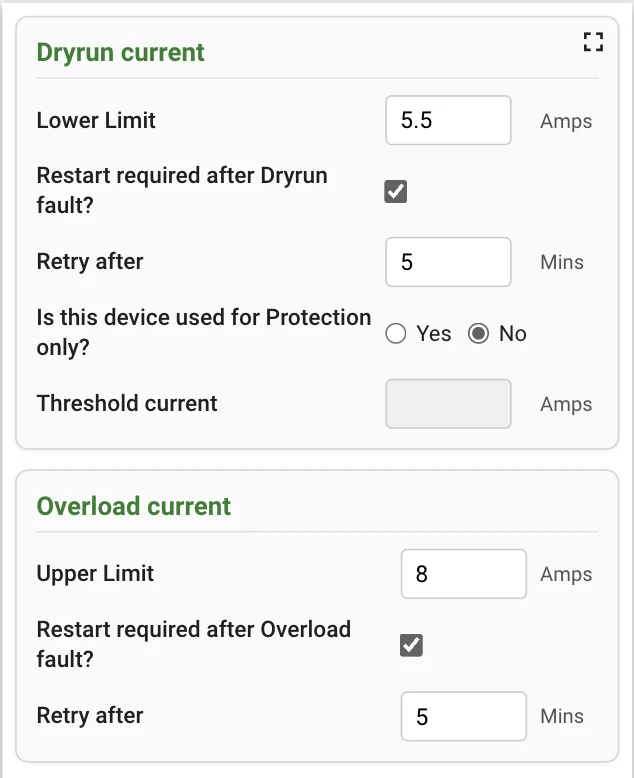
Dry-Run Protection (Under-Current)
Protects against the motor running without load (e.g., pump running dry when the water source is empty). When the current drawn by the motor falls below the configured lower limit for more than 4 seconds (after a 7-second startup grace period), the device trips and disconnects the motor.
- Lower Limit (Amps): Set the minimum current threshold. Set this slightly below the normal running current of your motor.
- Auto-restart: When enabled, the device automatically attempts to restart the motor after a configurable delay (in minutes). Useful when the water source may refill over time.
- Protection-only mode: For setups where the device monitors current but does not switch the load directly (e.g., Circuit 5 — booster pump with pressure switch, where the pressure switch does the switching based on the set pressure levels). The device reports the fault and disconnects the load only if there is a fault.
Overload Protection (Over-Current)
Protects against excessive current draw, which can indicate a motor jam, mechanical blockage, bearing failure, or short circuit. When current exceeds the configured upper limit for more than 4 seconds (after a 7-second startup grace period to allow inrush current), the device trips.
- Upper Limit (Amps): Set the maximum current threshold. Set this slightly above the normal running current but below the motor's rated maximum.
- Auto-restart: Use with caution for overload; repeated overloads may indicate a mechanical problem that requires physical inspection.
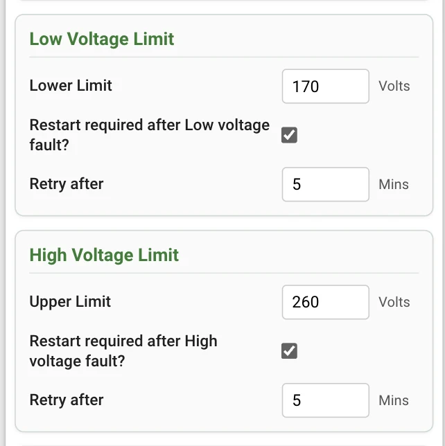
Voltage Protection
Protects equipment from dangerous voltage fluctuations. The device continuously monitors mains voltage and trips within 7 seconds if voltage goes outside the configured safe range.
- Low Voltage Limit: Default 150V. Motor trips if mains voltage drops below this value. Low voltage causes motors to draw excessive current, leading to overheating and potential winding damage.
- High Voltage Limit: Default 290V. Motor trips if mains voltage exceeds this value. High voltage can cause insulation breakdown and immediate motor damage.
- Auto-restart (Low V): Automatically reconnects when voltage returns to normal range, after the configured delay.
- Auto-restart (High V): Automatically reconnects when voltage returns to normal range, after the configured delay.
Additional Protection Settings
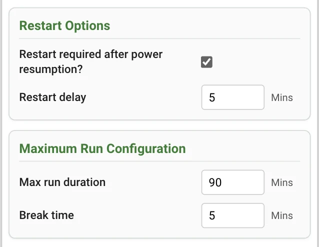
- Restart after power resumption: When enabled, the motor automatically restarts after a complete power outage (blackout). Useful for unattended installations like farm pumps or sump pumps.
- Restart delay (Mins): Wait time after power returns before restarting the motor. Allows the power supply to stabilize and prevents rapid on-off cycling. Recommended: 2–5 minutes.
- Max run Duration (Mins): Maximum time the device can run at a stretch. Acts as a safety backstop (e.g., if a float switch fails). Set to 0 to disable. If there is a maximum runtime limit for the motor or appliance, set it here.
- Break time (Mins): After the max run duration is reached, how long a gap or break should be given before running again.
Fault Detection Timing and Delays
The SwiGO SuperSmart uses specific timing sequences to distinguish genuine faults from normal operating transients:
- Startup grace period (7 seconds): When the motor is first switched ON, current readings are ignored for 7 seconds. This allows the motor's inrush current (which can be several times the normal running current) to settle down. Both dry-run and overload detection begin only after this grace period.
- Fault confirmation (4 seconds): After the startup grace period, if a dry-run or overload condition is detected, the device waits for 4 continuous seconds to confirm it is a genuine fault and not a momentary spike or dip.
- Voltage fault timing (7 seconds): Voltage faults are detected within 7 seconds. If the voltage exceeds the high limit or falls below the low limit and remains outside the safe range for 7 seconds, the device trips.
- LED blink duration (6 seconds): When a fault is detected and the device trips, the fault LEDs blink rapidly for 6 seconds to alert the user. After blinking stops, the LEDs remain in their fault state until the fault is cleared or auto-restart occurs.
- Retry after (delay timer): When auto-restart is enabled, the 'Retry after' field specifies the delay in minutes before the device attempts to restart. If the fault persists, the device trips again and waits for another retry cycle. This continues within the scheduled time period only — if the retry time falls outside the scheduled window, the device will not restart.
7.6 Settings Page (Gear Icon)
The Settings page provides access to all device configuration options. Tap the Gear icon in the navigation bar.
- Device time: View the current device clock and sync it with your phone.
- WiFi settings: View current connection details (Mode, SSID, IP, MAC). Change WiFi network, scan for available networks, set a static IP address.
- Device Name: Rename the device (e.g., Motor, Pump). After renaming, you must reconnect to the new AP name.
- Device PIN: Change the 4-digit security PIN.
- AP Password: Change the password for the device's own WiFi Access Point broadcast.
- Logs: View recent activity logs. Clear Logs to reset history. Reset Cumulative Energy to zero the kWh meter.
- Restart Device: Soft reboot. Clear Fault Conditions (override a fault trip without waiting for the retry timer — also overrides Manual Stop during a scheduled run). Logout Application.
- Cloud Settings: Connect or disconnect the EVIQtech Cloud (see Section 7.7).
- Firmware update: Shows current firmware version (e.g., 1.18.0). Upload the new firmware received.
- Float switch function: Configure float / flow switch modes (see Section 7.8).
- Master – Remote Control Configuration: Link devices together (see Section 7.9).
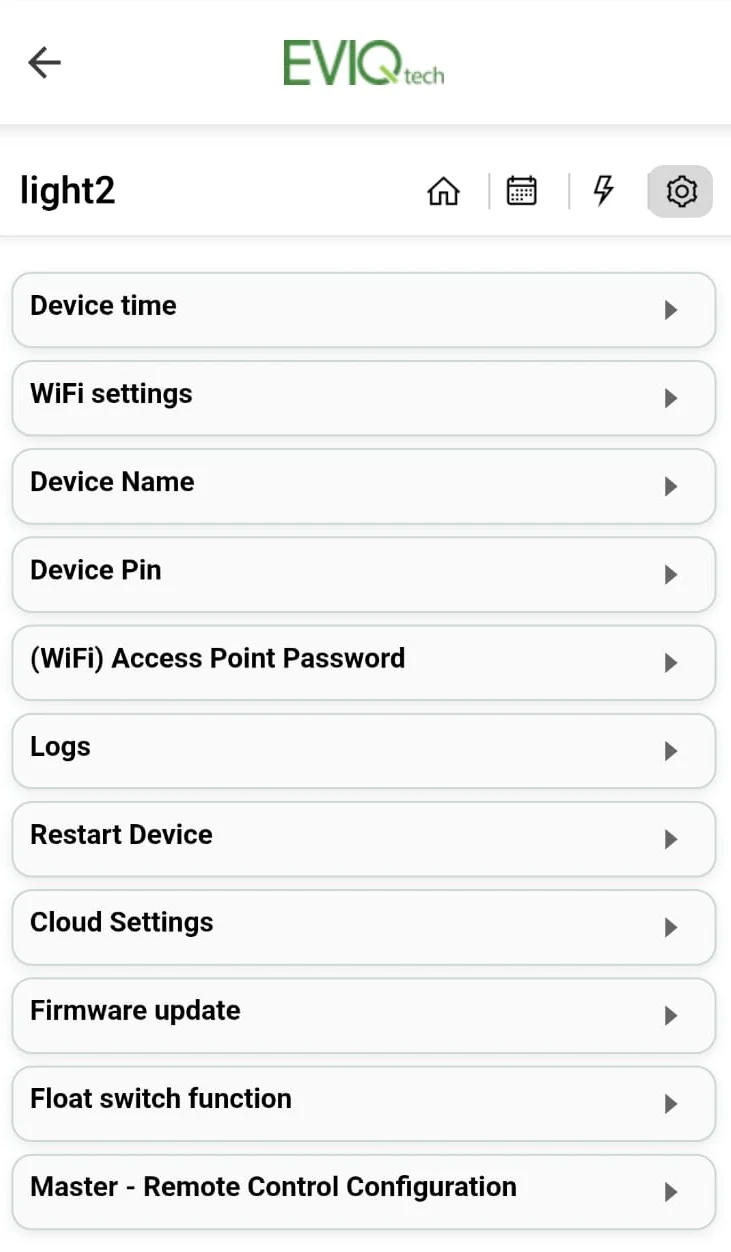
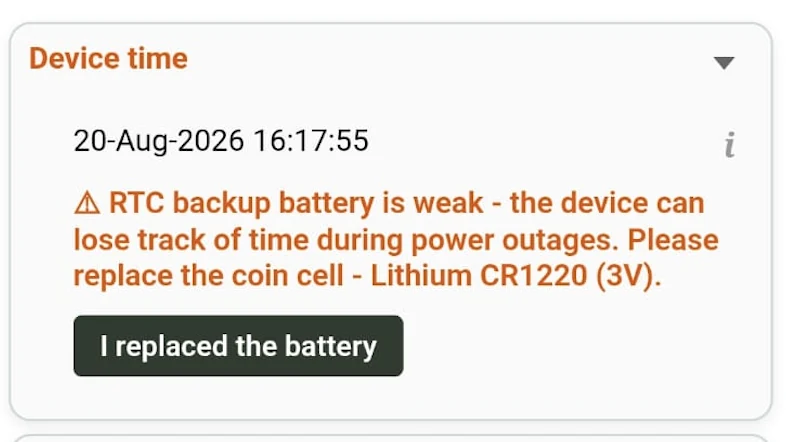
From firmware version 1.19.0, if the SuperSmart's RTC backup battery is weak, the Device time section is highlighted in red. After replacing the battery (Lithium CR1220, 3V), confirm it here by tapping I replaced the battery.
7.7 Cloud Settings
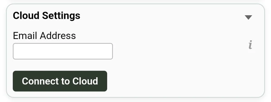
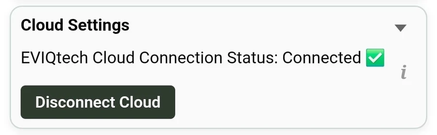
Cloud connection can be established or disconnected in this section.
- Enter your email address and click Connect to Cloud.
- Once an account is created, you will receive an email with a link to set the password.
- Note: If the device is already registered with another email and you try to give a new email, an error is shown.
- If the connection could not be established, please check:
- Internet is available
- No firewall is blocking the internet connection
- Firmware is 1.18.0 or above
7.8 Float Switch & Flow Switch Settings
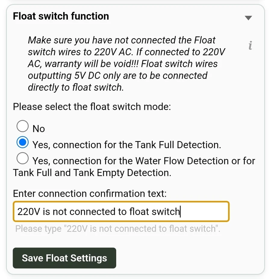
The SwiGO SuperSmart includes a 5V DC output for connecting a float switch or flow switch. This feature is configured at the bottom of the Settings page under Float switch. It enables automatic pump control based on water level conditions.
Understanding Float Switches (2-Wire and 3-Wire)
The SwiGO SuperSmart can work with both 2-wire and 3-wire float switches.
- 2-Wire Float Switch: Has a single NO (Normally Open) or NC (Normally Closed) contact. Suitable when you need only one detection mode — either Tank Full or Tank Empty. Connect the two wires directly to the 5V DC terminals (Red and Black wires).
- 3-Wire Float Switch: Has a common wire shared between two internal contacts (NO and NC). Supports both Tank Full and Tank Empty detection depending on which pair of wires you connect.
For a 3-wire float switch, depending on which pair of wires you connect to the 5V DC terminals, you get different detection behavior:
- Wire Pair A (Tank Empty detection): Connect the two wires that have continuity (circuit closed) when the float is hanging down (tank empty). When the tank fills and the float rises, this pair opens.
- Wire Pair B (Tank Full detection): Connect the two wires that have continuity when the float rises (tank full). When the tank is empty and the float hangs down, this pair has no continuity.
Option: No (Default)
Float switch functionality is disabled. The device operates on timer and manual control only. This is the factory default setting.
Option: Tank Full Detection (NO Contact)
Use this mode to automatically stop the pump when the tank is full. Connect Wire Pair B (continuity when float rises / tank full) to the 5V DC terminals.
How it works: When empty, the float hangs down and the circuit is open — the pump can run via timer, schedule, or manual control. As the tank fills and the float rises, the circuit closes and the device immediately stops the pump.
- Wire pair to use: Pair B — continuity when float is UP (tank full)
- Pump stops when: Float rises (tank full) — circuit closes
- Pump starts: Via timer, schedule, or manual ON only
- Use case: Overhead tank filling — pump runs until tank is full, then stops automatically
Option: Flow Detection or Tank Full/Empty Detection (NO Contact)
Use this mode to detect when the tank is empty and control the pump accordingly. Connect Wire Pair A (continuity when float hangs down / tank empty).
How it works: When empty, the float hangs down and the circuit is closed — the device can start the pump. As the tank fills and the float rises, the circuit opens and the pump stops. When water drops again, the float falls and the pump can restart automatically.
- Wire pair to use: Pair A — continuity when float is DOWN (tank empty)
- Pump runs when: Float hangs down (tank empty) — circuit closed
- Pump stops when: Float rises (tank full) — circuit opens
- Auto-restart: Yes — pump restarts when float drops again (tank empties)
- Use case: Fully automatic tank fill-and-stop cycle with no scheduling needed
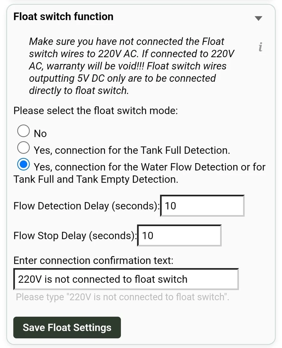
Flow Switch Option
A flow switch (paddle-type) can be connected to detect water flow in the pipe. When water flows, the switch remains closed and the pump runs. When flow stops (e.g., pipe blockage, dry pipe), the switch opens and the pump stops. This provides flow-based dry-run protection.
- Switch type: Paddle or flow switch — closed when water flows, open when no flow
- Use case: Dry-run protection based on actual water flow rather than current sensing
Delay Settings
When a flow switch option is selected, two delay fields appear:
- Flow Detection Delay (seconds): How long the device waits after detecting a switch state change before acting. Default: 10 seconds. Prevents false triggers from water sloshing or momentary float bouncing.
- Flow Stop Delay (seconds): How long after the switch opens before the pump is stopped. Default: 10 seconds. Provides a buffer to confirm the condition is genuine.
A safety confirmation text — "220V is not connected to float switch" — must be entered before saving.
Wiring Summary
| Mode | Wire Pair / Type | Float Position for Continuity | Pump Action |
|---|---|---|---|
| Tank Full Detection | 3-wire: Pair B / 2-wire: NO type | Float UP (tank full) | Stops pump when full |
| Tank Empty Detection | 3-wire: Pair A / 2-wire: NC type | Float DOWN (tank empty) | Runs pump when empty, stops when full |
| Flow Switch | 2-wire device | N/A — flow-based | Stops pump when no flow |
7.9 Master–Remote Control Configuration
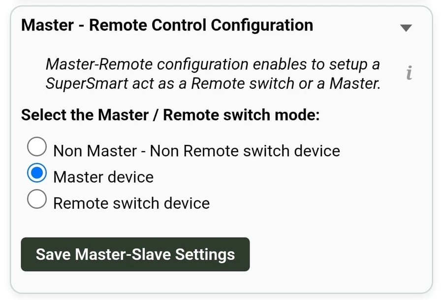
The Master-Remote feature allows multiple SwiGO SuperSmart devices to work together. One device acts as the Master and controls one or more Remote devices. When the Master switches ON or OFF, it sends a command to all linked Remote devices to do the same.
Three modes are available:
- Non Master – Non Remote switch device (Default): The device operates independently with no master-remote relationship.
- Master device: This device becomes the master. When it switches ON or OFF (via timer, schedule, or manual), all linked remote devices follow.
- Remote switch device: This device becomes a remote. It receives ON / OFF commands from its paired master device and follows them.
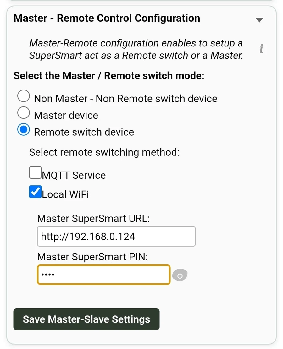
Remote Switching Method
When Master or Remote mode is selected, choose the communication method:
- MQTT Service: Uses the cloud (MQTT protocol) to relay commands between master and remote devices. Works over the internet — devices can be on different WiFi networks or locations.
- Local WiFi: Commands are sent directly over the local WiFi network. Both master and remote devices must be on the same WiFi network. Lower latency, no internet required.
8. Cloud Dashboard
The EVIQtech Cloud (powered by ThingsBoard v4.1.0) provides remote monitoring and control from anywhere. The cloud dashboard can be accessed from any device at https://iot.eviqtech.com once your device has been provisioned via Mode C (BLE pairing from the Android app).
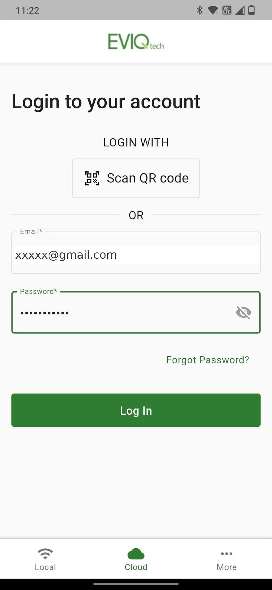
8.1 Logging into the Cloud
For new users: Tap the "Create Account" or "Register" option on the Cloud login screen, enter your email and set a password. Once registered, use these credentials to log in.
For existing users: Enter your registered email and password, or scan a QR code to log in.
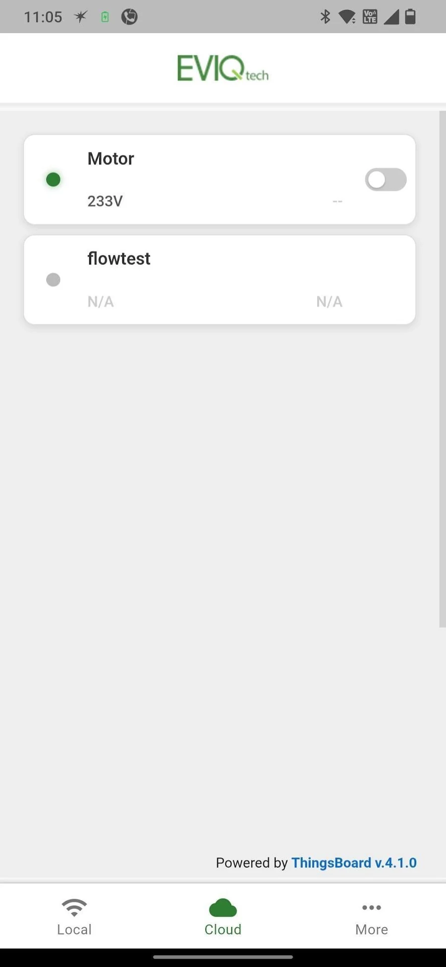
8.2 Multi-Device Overview
- Green dot: Online and cloud-connected
- Grey dot: Offline or unreachable
- Quick toggle: ON / OFF directly from the list
8.3 Cloud Home — Remote Control
- Countdown Timer: Shows remaining time during timed operation
- OFF / ON Toggle: Remote switch from anywhere
- Live Readings: Real-time voltage, current and power
- Logs: Remote actions are logged as "Started from Remote App" to distinguish them from local or physical button actions
8.4 Navigation Icons
- Settings / Filter: Cloud device config
- Home: Remote control panel
- Calendar: Cloud scheduling
- Lightning: Analytics and energy
- Plug: Protection status
8.5 Voltage-Current Analytics
- Realtime / History: Toggle between live and historical data
- Time window: Last, Range, or Relative
- Aggregation: None, Average, Min, Max
- Max values: Default 25,000 data points
8.6 Energy Chart
The Energy Chart displays cumulative energy consumption across configurable time ranges (hourly, daily, weekly, monthly). Useful for energy audits and usage tracking.
8.7 Cloud Scheduling
- + Add Schedule: Create new schedule
- Type: Daily or Weekly
- Start / End Time: Operating window for the schedule
- Is Cyclic: Enable repeating on/off cycles within the time window (see Section 7.4 for detailed explanation)
- Enable / Disable: Toggle schedule on or off without deleting
9. Browser Access (iOS, iPadOS, Desktop)
The EVIQtech Android app is available on Google Play. For all other platforms — iPhones, iPads, Macs, Windows PCs, and Linux — the SwiGO SuperSmart has a built-in web interface that can be accessed from any browser. No app installation is required.
9.1 Access via Local AP Mode (No Router Needed)
When the SwiGO SuperSmart is in AP mode (Access Point mode), it creates its own WiFi network. You can connect to it from any device and access the control interface through a web browser.
http://192.168.4.1 and press Enter.http://192.168.4.1 (AP mode) and http://DeviceName.local (WiFi mode) for quick access. The session times out after 10 minutes of inactivity.
9.2 Access via Local WiFi Mode (Same Network)
Once the SwiGO SuperSmart is connected to your home or office WiFi router, you can access it from any device on the same network using a browser.
- mDNS name:
http://DeviceName.local(e.g.,http://motor.local) - IP address:
http://[IP assigned by router](e.g.,http://192.168.0.120) — check your router's DHCP client list if needed
9.3 What You Can Do via Browser
The browser interface provides the same functionality as the Android app's Local tab:
- View real-time power monitoring (voltage, current, power, energy)
- Turn the load ON / OFF manually
- Set and manage timer duration
- Configure schedules (daily, weekly, and cyclic)
- Adjust protection settings (dry-run, overload, voltage limits)
- Configure float switch and flow switch modes
- Set up Master-Remote control
- Change device name, PIN, and WiFi settings
10. Troubleshooting
10.1 Device Not Found During BLE Scan
- Ensure BLE mode is active: Hold Green + Yellow buttons 5s until blue LED blinks
- Bluetooth enabled on phone
- Move closer to device (within 5 meters)
- Location permission granted to the app
- Restart device and retry
10.2 WiFi Connection Fails
- Double-check WiFi password
- Confirm 2.4 GHz network (5 GHz not supported)
- Router online and in range
- Restart router and device
10.3 Cloud Connection Not Working
- Verify cloud email is correct
- Internet connection active
- Device connected to WiFi first (check Local tab)
- Log out and back in on Cloud tab
- Force-close and reopen app if stuck on Loading
10.4 Device Offline in Cloud
- Device powered on and WiFi connected locally
- Internet connection working
- Update WiFi via Settings if network changed
- Restart or power-cycle the device
10.5 Returning to AP Mode
If WiFi is unavailable, the device auto-returns to AP mode in approximately 15 seconds. To force it manually:
- Hold Violet + Red buttons 10 seconds until blue LED lights up
10.6 Factory Reset
- Hold Yellow + Blue + Red buttons 20 seconds until blue LED lights
10.7 PIN Forgotten
The SwiGO SuperSmart PIN is user-defined and is never the default "1234" after Initial Setup. If you forget your PIN:
10.8 iOS / Browser Interface Not Loading
- Confirm you are connected to the correct WiFi (SwiGOss_AP in AP mode, or your home WiFi if the device is configured)
- Try the IP address instead of the .local name:
http://192.168.4.1(AP) or the router-assigned IP (WiFi mode) - Disable mobile data temporarily — some phones prefer cellular over the device's AP
- Clear browser cache and reload
- If using AP mode, confirm your device has not automatically disconnected from SwiGOss_AP (some phones prompt "No internet — use this network?"; choose to keep it)
11. Support and Contact
For technical support, warranty inquiries, or feedback:
| Contact | Details |
|---|---|
| Website | www.eviqtech.com |
| info@eviqtech.com | |
| Cloud dashboard | https://iot.eviqtech.com |
| Android app | Via the "More" tab in the EVIQtech app |
Thank you for choosing EVIQtech!
© 2026 EVIQtech. All rights reserved.